We now review the method for computing Haar coefficients: we
restrict our attention to a sequence of eight samples  (which can be thought of as averages on intervals of length
 of a function defined on
  ). The first
computation involved
). The first
computation involved
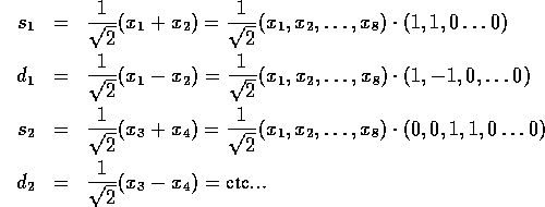
Observe that the transformation from x to  and
and  consists of a string of rotations by
  of the vectors
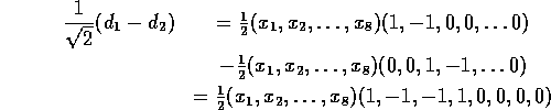
 . Therefore,
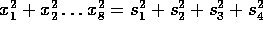
 , i.e. the
total energy is conserved.
, i.e. the
total energy is conserved.
In the second stage we view  as new samples (they are
``averages'' on intervals of length
as new samples (they are
``averages'' on intervals of length  ) and repeat the
procedure, computing sums of sums
) and repeat the
procedure, computing sums of sums  and differences of sums
 .
.
It is natural to also view the differences  (which
measure the variation of the samples) as a new signal and perform the
same transformations on them.
(which
measure the variation of the samples) as a new signal and perform the
same transformations on them.
 corresponding to average variation.
 corresponding to change in variation.
and continuing to fill in the rectangle, row by row, as in figure A.16.
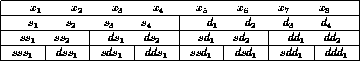
Figure A.16: A rectangle of Haar wavelet packet coefficients
(This procedure will be interpreted later as subband coding).
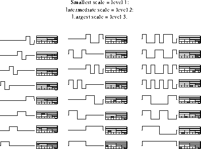
Figure A.17: Haar wavelet packets on  :
:
We observe that each entry in this rectangular array of numbers
represents an inner product of the original signal  with a multiple of a vector with entries
  as described in the
following diagrams:
as described in the
following diagrams:
For example, the entry  is obtained by taking
which is the pattern corresponding to the first box in the
4 block on level 2 (the signal is on level 0).
The patterns (or vectors) generated in the preceding pages can be combined in different ways to construct orthogonal basis of eight dimensional space.
The last eight patterns on level 3 represent the well known Walsh pattern functions (providing a square wave Fourier analysis). Clearly the transform mapping the original sequence into the entries of the bottom row is orthogonal (since it was obtained by a succession of orthogonal transformations). Therefore the different patterns which are the columns of this transformation are orthogonal. The basis corresponding to a fixed row provides a windowed Walsh transform.
The discrete Haar wavelet basis is obtained by choosing the second block in each row and the first and second entry on the last row.
It is easy to see that any collection of blocks in the rectangle with
the property that their shadow intervals form a disjoint cover of the
full range provides a collection of patterns forming a basis. As can
be seen on the following example diagram, we use the entries on the
bottom level (3) to recover the entries on the ``parent'' box above
these entries. We then use the entries on level 2 to recover all
entries on level in the parent box. We now have a full set of entries
on level one enabling us to recover the original signal. Since all
transformations were orthogonal we must have that the collection of
vectors corresponding to this choice of patterns is an orthogonal
basis of  .
.